This paper studies the impact of common interferers found in unlicensed bands on 802.11 and other CSMA systems. First, we describe those interferers and the MAC techniques used to combat them. Then, we present Fragment Adaptive Reduction, a scheme to overcome the effect of non CSMA repetitive interferers, and it's implementation in the SWAP protocol. We also describe a simple model of domestic microwave oven interferences. We finish by some exhaustive simulations of the impact of microwave oven and other interferers on 802.11, which illustrate the benefits of the Fragment Reduction scheme.
The physical layer is already doing a lot to combat those interferences, through clever modulation techniques (Spread Spectrum, OFDM) and reception techniques (diversity, equalisation). But, some MAC layer schemes can also improve performance and avoid loosing connectivity.
The fact that the band is unlicensed means that the deployment of such systems doesn't require any planning permissions, so system may be deployed in an anarchic way and interferer with each other if they are within range.
The ISM rules allow a wide variety of products to operate in the band, such as standard 802.11 wireless LANs [1], fast hopper systems (such as BlueTooth [3]), cordless phones or TV redistribution systems, which make use of it in different ways even if they obey the same basic rules.
Domestic microwave ovens are more predictable and easier to characterise (we describe a model of it in section 5.4.3). However, industrial microwave ovens (like in factories) may be much stronger and wider emissions, and a few microwave ovens on different phases might create permanent interference in the band.
Attenuation is due to the distance and obstacles on the path between transmitter and receiver, a good sensitivity allows the system to work at higher attenuation.
Fading is due to obstacles and reflections, the channel alternating between "good" and "bad" state. Antenna diversity significantly reduces the effect of fading.
Delay spread is due to the different components of the signal not arriving at the same time at the receiver, it is overcome by using equalisation and OFDM.
At this point, because there is virtually no product deployed, it is difficult to say if the 5 Ghz band is better than the 2.4 GHz band with respect to interference...
Retransmission eventually overcomes all kind of interference. Other techniques are only minimising the amount of retransmissions and the overhead.
There is only one exeption : some repetitive interferers may hit all retransmissions of a packet, up to the point where the MAC drops it (see section 6.1).
CSMA/CA [1] is based on carrier sense and a slotted contention, the initial number of slots fixed, with exponential increase. It would benefit from a distributed adaptive scheme [6] to select the optimal initial contention window (CWmin).
Most systems also perform virtual carrier sense through the use of RTS/CTS [4], which improves carrier sense information, eliminates hidden node effects and reduces the penalty of collision (shorter collisions).
Carrier sense and RTS/CTS are very efficient when interferers are also CSMA/CA based, but much less with microwave ovens or non CSMA systems.
Systems based on TDMA and Polling can naturally control the scheduling of packets. The contention of 802.11 has a memory effect (nodes having waited the most have a lower count of slots), so tend to schedule packets as well, but this supposes that there are multiple active nodes at once.
Channel State Dependant Packet Scheduling [5] complements this by having a node
scheduling packets based on destination addresses. A much simpler
version of it is, after a failure, to just pick and transmit the first
packet in the transmit queue with a different destination address,
before retransmitting the failed packet (without any attempt at
scheduling). Of course, this supposes that the node has traffic for
many other nodes and not just a single destination.
3.5 Auto rate selection
Increasing the bit-rate decreases the range and vice versa, so most
products implement multiple bit-rates. When transmitting a packet, the
node tries the fastest rate and falls back to lower rate (more robust)
in case of failures. This is usually very efficient to overcome
attenuation and pretty good with fading.
But, this is not always the best strategy, because decreasing the rate increases the transmission time. If the packet was lost because of an interferer, increasing the transmission time will increase the probability of collision, which is not what we want.
In fact, auto rate selection algorithm should not only take into account packet failure but also received signal strength and RTS/CTS failures to make the decision (see section 4.4).
802.11 [1] provides a very efficient fragmentation mechanism, where fragments are sent as a contention free burst. However, fragmentation is fixed (no variation of fragment size) and adds a significant overhead when we don't need it (no interferers), so most 802.11 products don't use it.
When there is no interferer, packets are sent unfragmented to minimise overhead, and in presence of repetitive interferer the fragment size is reduced until the packet can fit between the bursts of the interferer. The scheme doesn't make any assumption about the nature of the interferer and just adapts to it, so that it works well for all kinds of interferers.
There are two types of adaptation, long term adaptation and short term
adaptation. Transmission conditions and interferer emissions do change
a lot and quickly, especially with frequency hopping, which usually
defeats long term adaptation. The lifetime of the packet in the system
is short, so if we want every packet to benefit from it and not to
loose any packet, we need short term adaptation.
4.3 How to reduce fragments
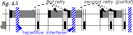
The easiest solution to reduce fragments is to link the maximum
fragment size to the number of transmission failures (acks not
received) experienced by a packet, so having an exponential number of
fragments (see fig. 4.3).
In our scheme, each packet is initially transmitted without fragmentation and for each failure the fragment threshold is divided by two until reaching the minimum adapted fragment size (to prevent ridiculously small fragments). We are only reducing the fragment threshold, so small packets will be fragmented only if and when the fragment threshold gets lower than their size.
However, we can't assume that packet failures are always due to interferers, in fact the contention process is the source of many collisions [10]. Because of the exponential increase of the contention window, the first failure is very likely to be a contention, and subsequent failures more likely to be due to interferers. Therefore, a good strategy is to postpone fragment reduction after the second or third failure.
In our model, we tried both after 1 failure (Autoreduce 1) and after 2 failures (Autoreduce 2), which work as follows :
| Packet failures | Autoreduce 1 | Autoreduce 2 |
|---|---|---|
| 0 - Initial transmission | 2048 B | 2048 B |
| 1 - After one failure | 1024 B | 2048 B |
| 2 | 512 B | 1024 B |
| 3 | 256 B | 512 B |
| 4 or more failures | 256 B | 256 B |
Now, if after reducing fragment size a fragment is successful, we
could assume that we have reached the correct fragment size. So, I
have simulated a modified scheme, where when a fragment is successful,
fragment reduction is held off for the next failure and resumed only
at the second failure after this successful fragment. In practice,
this didn't make much difference, so I only present schemes that
always reduce fragment size on failure (apart from the very first
one).
4.4 Interaction with other schemes
Decreasing the bit rate increases the transmission time (see section 3.5), so the reduction scheme must
compensate for that effect. For example, when dividing by 2 the
bit-rate, we should divide the fragment threshold by 4 (and not by 2).
My current model doesn't distinguish between RTS/CTS failures and packet failures, because I wanted to have results valid also for networks not using RTS/CTS. Distinguishing the two types of failure can significantly improve the performance of fragment reduction (and adaptive bit rate). If the RTS/CTS fails, it is likely a contention issue, so no action should be taken. However is the main transmission protected by the RTS/CTS fails, this is likely a interference issue, and fragment size should be reduced (and bit-rate as well).
In another paper I present adapting fragment size to fit in the dwell [11]. These two adaptation schemes are compatible, in fact my simulations implement both adaptive schemes.
| Packet failures | 1 Mb/s | 2 Mb/s |
|---|---|---|
| 0 - Initial transmission | 512 B | 1024 B |
| 1 - After one failure | 512 B | 1024 B |
| 2 - reduce bit-rate | 256 B | Forbidden |
| 3 | 128 B | Forbidden |
| 4 or more failures | 64 B | Forbidden |
The model implements MAC level acknowledgments and retransmissions. The model includes RTS/CTS (for packets larger than 250 B), dwell adaptive fragmentation and when stated fixed fragmentation or fragment reduction. The minimum adapted fragment size is 256 B.
By default, the maximum packet size is 2048 B. All other defaults parameters conform to 802.11 [1] (CWmin = 16 ; SIFS = 28 µs ; Slot = 50 s ; Hop delay = 224 µs ; Headers = 50 B ; Ack/RTS/CTS = 30 B ; MaxRetries = 7). Some simulations use different values for some of those parameters.
The receiving node acknowledges incoming packets with short packets (40 B). The probability of small packet is 1/3 (the receiver sends a small packet for each received packet with a probability 1/2).
To worsen the model, the exponential backoff has been removed, the model starts first in the dwell, the pathloss to simulated nodes is reduced to 60 dBm, and the model doesn't implement RTS/CTS or fragmentation.
A microwave oven is composed of a magnetron, powered by the AC mains, and producing the radiation. Therefore, emissions have a 50 % duty cycle based on the mains period (60 Hz in the US). Each emission starts by a transition phase, where the emissions swipe across the band, before the magnetron settle on its main frequency, and again a transition phase before shutting off. Those transition phases are the most damaging, because they pollute a wider band, albeit at a lower power, while the main burst is very localised.
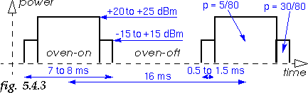
The model of microwave oven used in the simulations is described in fig. 5.4.3, with timing, signal strength and probability of presence selected using uniform random variables in the described range. Power and timing are calculated for each burst, probability of presence for each dwell (this hack is used to simulate our own frequency hopping by making the interferer come and go). The pathloss between the microwave and the system is 60 dBm.
The model simulates a TDMA link between two nodes in close proximity. The dwell size is 625 µs, in each dwell the model transmits a 366 µs packet at 0 dBm power (1 mW) and then hop. The hopping rate is effectively 1600 hops/s. Each packet has a 5/80 probability to be in our channel.
We simulate four systems in presence of the microwave oven interferer, a standard 802.11 system (Standard), the same system with fixed fragmentation (2 fragments), and two fragment reduction scheme (Autoreduce 1 : reduce fragment size on first failure ; Autoreduce 2 : reduce fragment size on second failure). Each system simulates a TCP transfer between two nodes using the TCP1 model. For reference, the standard 802.11 system is simulated without microwave oven interferer (No MWO).
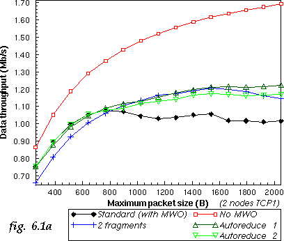
The first curve shows the throughput of each system at different packet sizes (fig. 6.1a). Fragmentation schemes can reduce the impact of the interferer in the band. Fragment reduction always gives the best results whereas fixed fragmentation needs to be tuned up to the interferer.
But, the most important measure is the percentage of packets dropped by the MAC. All MACs include up to 7 MAC level retransmissions for every packet, but if the packet fails 8 times it is dropped. TCP/IP is very sensitive to packet drop (it assumes congestion), some small packet drop rate (like 1 %) can reduce significantly the throughput [7], and the loss of some specific packets can break the connectivity.
This measure is also important for multimedia traffic. While the node is "locked" retransmitting the same packet 8 times (around 100 ms), other packets wait in the queue and their latency is impacted. In fact, when the dropping rate is high, the MAC is likely to be blocked for the whole dwell time (200 ms). So, latency is linked to packet drop rate.
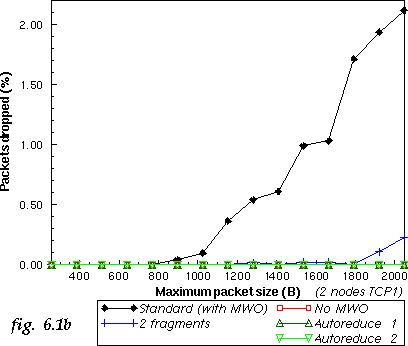
At standard packet sizes, the Standard system performs
poorly (see fig. 6.1b), because large
packets are repetitively hit by the interferer (the channel is
blocked). But even when packet size is half the interval between burst
(1000 B) we start to see losses. By automatically reducing the
fragment size (Autoreduce) we can make sure that packets
eventually can get through between interferer bursts and no packets
are lost.
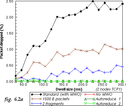
6.2 Influence of dwell size
In the previous simulations, packets get dropped because the system
stays for a long period of time on the same frequency as the
interferer. As the system is Frequency Hopping, by reducing the dwell
size we minimise the length of time we have to cope with the
interferer.
To verify this, we simulate our 5 previous systems with different dwell size (at the maximum packet size, 2048 B). We add another system with a reduced packet size (1500 B packets). Reducing the dwell reduces the number of packet dropped by all systems (see fig. 6.2a). Of course, only fragment reduction can prevent all losses.
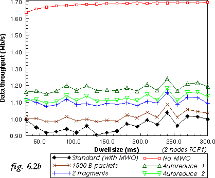
Some people have claimed that reducing the dwell size increase the throughput, and that fast hopper systems [4] should perform better. The hopping rate doesn't change the probability of hitting frequencies polluted by the interferer, as can be seen on the throughput curves (see fig. 6.2b).
6.3 Influence of contention
Interferers are not the only cause of packet losses, the contention
process also contributes to losses [10]. In
this simulation, a network of nodes using the TCP2 traffic
model is used with an increasing number of active nodes. The same
MAC configurations as previously are simulated, but this time without
the microwave oven interferer. Two additional systems with the
microwave oven are simulated (Standard with MWO and
Autoreduce 1 with MWO).
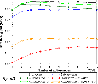
The first thing to notice is that fragmentation does reduce the network performance when no interferer is present in the band (see fig. 6.3). Fixed fragmentation has a constant penalty (2 fragments), whereas the fragment reduction schemes overhead increases with the amount of contention.
Because it reduces fragments only after the first retry, Autoreduce 2 performs better than Autoreduce 1, which confirms our analysis (see section 4.3). Of course, distinguishing failures of RTS/CTS (mostly due to contention) and failures of packets (mostly due to interferer) would allow to remove most of this overhead and the need for the Autoreduce 2 scheme.
Another interesting thing is that the performance of Standard
802.11 with MWO does increase with a higher number of nodes. A
higher number of active nodes does a better scheduling of packets and
takes advantage of frequency diversity (retries are separated by
packets from other nodes and pushed to the next hop, see section 3.4).
6.4 Other interferers
Microwave interferers are not the only kind of interferers in the 2.4
GHz band. So, we have simulated our system in presence of different
types of interferers : a CSMA frequency hopping system
(with FH), a CSMA direct sequence system (with
DS), a microwave oven (with MWO) and a TDMA fast
frequency hopper system such as BlueTooth (with BT).
The system studied is a TCP transfer between two nodes using the TCP1 traffic model and 1500 B maximum packet size. Each interferer is placed at 60 dBm of our system, and the distance between the two nodes varies from very close (50 dB attenuation) to the limit of the range (95 dB).
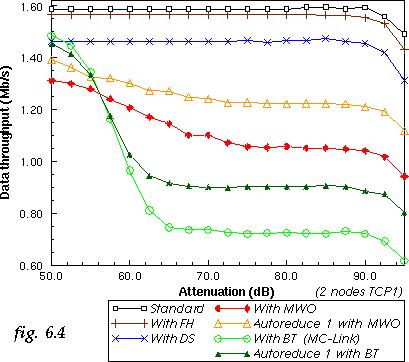
The best way to deal with other CSMA systems is to use CSMA (and RTS/CTS), and the degradation in the cases With FH and With DS is quite low (see fig. 6.4). The only way this impact could be greater is if the interferer use a much smaller contention slot or having multiple nodes instead of one. Adding Fragment Reduction may reduce performance due to the increased contention (see section 6.3).
Results with a microwave oven are similar to previous sections. When the two nodes get closer, they gradually capture packets. It's because most of the packet corruptions are due to the wideband transition phase which are relatively low power, so not strong enough to corrupt packet received at high level (in my model, the capture starts to occur when the wanted signal is around 22 dB stronger than interferers).
The fast frequency hopper (With BT) brings a lot of performance degradation of the system. The system emit short bursts all over the frequencies, making sure that any packets long enough will get hit. Fragment Reduction (Autoreduce 1 with BT) does help a lot, but not as much as in the microwave oven case, because the fast frequency hopper cycles frequencies so fast. Using a periodic model for frequency hopping instead of the current random model would probably help fragment reduction to perform better.
When the two nodes get closer, they of course can capture most packets because the fast hopper is low power, but they need to get really close. Note that in this case, Fragment Reduction do perform worse, because hits tend to be occasional, so there is no benefit from fragmenting.
However, 802.11 and most CSMA/CA protocols don't deal very efficiently with the interferences produced by microwave-ovens and fast frequency hopping systems.
By automatically reducing fragment threshold when transmission fail, a
system can avoid dropping packets in presence of repetitive interferes
and significantely improve performance. This simple technique can be
easilly implemented in 802.11 and most CSMA/CA systems.
9 References