This paper studies the impact on CSMA/CA traffic of a reduction of the dwell size, a fundamental parameter of some wireless LANs. First, we explain why we want to reduce the dwell size and what are the consequences. Then, we present some ways to overcome the overhead of short dwell, mostly based on fragmentation. We finish by some exhaustive simulations of the short dwell size impact and variations, and the way those fragmentation schemes improve the network performance.
When it comes to some essential parameters of the MAC protocol, there is no absolute answer and each designer has to set them according to the constraints, traffic patters, operating environment conditions and the results of simulations.
The dwell time is one of those parameters, where the radio constraints invite for a small value but network traffic prefers a large value, and the MAC designer has to compromise...
The system uses a set of frequencies for transmissions and cycle through them periodically. Common systems use a fixed hopping rate and a fixed hopping pattern.
Consequently, the system stays only a limited fixed time on each frequency before hopping to the next frequency in the sequence. The time between two hops is linked to the hopping rate and called the Dwell time.
More importantly, this reduction of dwell size allows to decrease the latency of the system : the system stays a shorter time on the bad channels, where transmissions may be blocked [6], and move more quickly to a good one. Decreasing the latency helps with TCP congestion control algorithm and for multimedia applications.
To optimise the isochronous node operations (guarantee of delay, codec synchronisation, power saving...), this frame must come at fixed regular interval [2] and this interval be short (typically 10 to 20 ms).
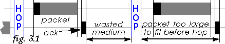
However, the main reduction of performance is not so much the time between the two dwells, but the time lost at the end of each dwell due to the granularity of the transmissions. Each transmission must fit entirely within the dwell, so if the time remaining before the end of dwell is shorter than the transmission time of the packet to send, the packet has to wait for the next dwell and this time is lost (see fig. 3.1).
This overhead is sometimes increased because some implementations use
crude approximation to make this comparison (coarse timers, assume all
packets are of maximum size) or some protocols have non predictable
packet transmission time (HDLC stuffing provides an expansion factor
between 0 and 5 % difficult to estimate).
3.2 Dwell size and packet size
One simple solution would be to adapt the dwell size to the packet
size or vice versa. This is usually not possible.
The hopping rate is usually constrained by the requirement of the isochronous traffic (latency) and fixed. Moreover, isochronous traffic has precedence over CSMA/CA, so the dwell size available to CSMA/CA depends on the current isochronous traffic requirement and may vary in time.
Packets sizes and their distributions are usually fixed by the applications and the MAC has little control over this. This alone prevents hardcoded optimisation between dwell size and packet size (see section 6.2).
Of course, no MAC designer would design a MAC having such a short
dwell, but as mentioned above, an increase of the isochronous traffic
may reduce the dwell size, so this case may happen when there is too
many isochronous connections.
4 Remedies : fragmentation
When the dwell become shorter, the time lost at the end of the dwell
may become a very significant overhead (see section 6.1), and packets blocked are
definitely to avoid.
802.11 offers an efficient fragmentation scheme [1], designed to reduce the impact of channel errors. Fragments are of fixed size and sent in a contention free frame, the receiver automatically performing the reassembly of the original packet (see fig. 4.1).
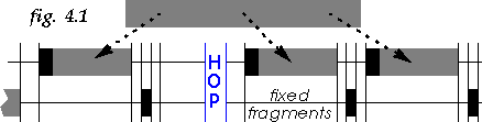
A typical implementation (like my model) would use a fixed threshold and split a packet evenly in fragments smaller than the fragmentation threshold.
Fragments, because they are smaller, fit better in the dwell, so can use more efficiently the time at the end of the dwell and avoid being blocked. On the other hand, fragmentation adds a significant overhead (a header and an ack transmission for each fragment - see section 7.1).
In fact, there is no reason why we can't do that. The sender can choose on the fly prior to transmission the ideal fragment size (allowing the fragment to fit perfectly in the remaining dwell) and changing the fragment size in case of retransmission (see fig. 4.2).
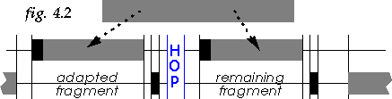
The only magic is in the receiver implementation : it must always replace an old fragment in favor of a retransmission of it and keep two pointers in the received buffer, one on the last byte received (for receiving a new fragment) and one on the beginning of the last fragment received (for replacing it).
The transmitter would use 3 parameters to control the adaptive fragmentation scheme : the fragment threshold (maximum size of fragments), the minimum adapted fragment size (minimum size of fragments it can create) and the minimum remaining fragment size (minimum size of the last fragment). The minimum adapted fragment size prevents creating ridiculously small fragments (which are inefficient) and allows to leave the last part of the dwell reserved for small packets (which improves performance - see section 6.6).
As multicast transmissions are less used and usually not performance critical, we can tolerate the overhead they have. However, the prospect of packets blocked is not welcomed. But we can't use fragmentation, and most networking stacks doesn't allow to set a maximum packet size (MTU) different for multicast packets than unicast packets.
In fact, if the case arises when the full dwell can't accommodate a multicast packet, the only practical solution would be to simply drop the multicast packet ! Multicast transmissions have never been reliable on wireless protocol [5], so this would be no big surprise for most applications...
The model implements MAC level acknowledgments and retransmissions. When stated, the model includes RTS/CTS (for packets larger than 250 B), fragmentation or adaptive fragmentation.
By default, the maximum packet size is 1500 B. All other defaults parameters conform to 802.11 [1] (CWmin = 16 ; SIFS = 28 µs ; Slot = 50 s ; Hop delay = 224 µs ; Headers = 50 B ; Ack/RTS/CTS = 30 B ; MaxRetries = 7). Some simulations use different values for some of those parameters.
The receiving node acknowledges incoming packets with short packets
(40 B). The probability of small packet is 1/3 (the receiver
sends a small packet for each received packet with a probability 1/2).
6 Dwell overhead : simulation results
Many simulations have been performed to study the impact of the dwell
size variations and how fragmentations and adaptive fragmentation can
cope with that. All the simulations have been implemented under the
Bones® Designer environment.
6.1 Impact of traffic model
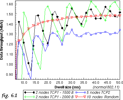
In this simulation, we use 3 different traffic models and network
setups. The first system simulates a TCP transfer between two nodes
using the TCP1 model, the second system is 5 nodes sending TCP
traffic using the TCP2 model and the third system is 10 nodes
using the random traffic.
The 2 nodes TCP1 system is the most sensitive to dwell size variations (see fig. 6.1). The curve shows clearly the dwell size where we can fit one 1500 B packet, and then two, and three, and that the increase of the dwell decreases performance until we can fit one more packet in it (because of the time wasted at the end of it). The curve also shows that below 8 ms the packets are simply blocked.
On the other hand, the 10 nodes random system is much less sensitive to dwell size. Having a larger number of transmitters and random distribution of packet size give a high probability of having one node who has a short packet that can fit in the time before the end of the dwell. In this case, the main overhead is the hop time itself.
The 5 nodes TCP2 system is also quite sensitive to the dwell size, due to the large number of large packets.
6.2 Impact of packet sizes
Changing the packet size affects how packets fit in the dwell (see section 3.2). With larger packets (2000 B
instead of 1500 B), the impact of the dwell overhead on the 2
nodes TCP1 system is increased (higher jitter), as well as the
dwell size where packets are blocked (see fig. 6.1).
6.3 Impact of contention slot size
The size of the contention period is an important performance factor
in most MAC protocols [4]. The size of the
contention slot, like the size of the SIFS, is mainly governed by the
physical layer RxTxTurnaround time. 802.11 uses
20 µs, SWAP uses 34 µs, Proxim OpenAir uses
around 200 µs and we can expect 100 µs from DECT
chipset.
To illustrate that effect, we simulate the 2 nodes TCP1 system with the normal 20 µs RxTxTurnaround time and with 100 µs (see fig. 6.3). Increasing the RxTxTurnaround time has of course a negative impact on CSMA/CA performance, because it makes contention longer. The only effect with regards to dwell overhead is to move the curve horizontally, because with an increased RxTxTurnaround time the dwell needs to be larger to fit the same number of packets.
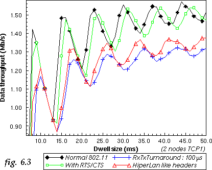
In this simulation we compare the 802.11 overhead with the HiperLan overhead for a 2 nodes TCP1 system (see fig. 6.3). Increasing the header size has globally the same effect as increasing the RxTxTurnaround time, lowering the throughput and shifting the curve to higher dwell.
Again, this shifts the curve to higher dwell (see fig. 6.3). However, as opposed to the
increase in slot size or header size, the performance with RTS/CTS may
be higher than the normal system because RTS/CTS reduces collision
penalty.
6.6 Latency differences
Probably the most interesting effect of a short dwell is on the
latency of small and large packets.
A limited dwell size means that often large packets are postponed from one dwell to the next, because the remaining time is too short for their transmission. The net effect is that the latency of those packets is increased.
However, for small packets, the situation is different. These packets can usually fit perfectly in the end of the dwell. In fact, because big packets are postponed, the bandwidth at the end of each dwell is like "reserved" for them.
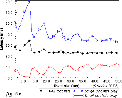
In this simulation, we compare the average latency of small and large packets for the 5 nodes TCP2 system (see fig. 6.6). With the reduction of dwell size, the latency of large packets tend to increase (matching the throughput curve) while the latency of small packets can be very close to 0 ms.
Reducing the fragment size reduces dramatically the impact of the jitter (see fig. 7.1), and the smallest fragment size offer a very smooth curve. On the other hand, we can see that fragmentation carries a significant overhead.
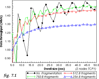
In fact, for each dwell size, there is an optimal fragment size which gives a good tradeoff between the reduction in jitter and reduction of throughput. For example for SWAP [2] we have chosen a fragment threshold of 512 B at 1 Mb/s and 1024 B at 2 Mb/s (SWAP has a 20 ms dwell, 1 Mb/s is almost equivalent to a 10 ms dwell in those simulations).
To verify the impact of dwell adaptive fragmentation, two additional 2 nodes TCP1 systems are simulated. The first one has a fragment threshold of 1500 B and a minimum adapted fragment size of 256 B, so it fragments packets only when needed and can leave space for 2 small packets at the end of the dwell. The second one has a fragment threshold of 512 B and minimum adapted fragment size of 128 B, so fragments packets in 512 B fragments or smaller. In both case the minimum remaining fragment size is 0 B. Those systems are compared to fixed fragmentation with 1500 B and 512 B fragment threshold.
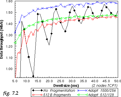
Dwell adaptive fragmentation almost totally removes the jitter produced by short dwell size (see fig. 7.2) and provides a substantial performance enhancement for short dwell. Dwell adaptive fragmentation with maximum fragment threshold always outperform other schemes, so the fragment threshold no longer needs to be tuned to the dwell size.
In fact, dwell adaptive fragmentation almost totally removes the overhead of small dwell (apart from the hop time itself and the fragmentation overhead).
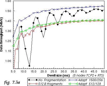
In this simulation, the improvement offered by fragmentation and adaptive fragmentation is slightly smaller (see fig. 7.3a), because the impact of short dwell was smaller to start with (more nodes and more small packets). But adaptive fragmentation still outperform other schemes.
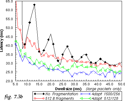
As we can guess, fragmentation has also an impact on the latency of the system. Short dwell has a tendency to increase the latency of large packets. To verify the impact of fragmentation, the latency of large packets for the 5 nodes TCP2 system in the same setup is measured (see fig. 7.3b). Adaptive fragmentation removes most of the jitter and offers a nice reduction of the latency for large packets.
When the dwell is short, this wasted time becomes very
significant. Fixed fragmentation with a judicious choice of the
fragment threshold allows to reduce this overhead. Dwell adaptive
fragmentation adds only a little more complexity to fixed
fragmentation but increase significantly the performance of the system
and is much more versatile.
9 References