
This paper presents a scheme to improve the performance of radio MAC protocols in the case of TCP/IP multimedia traffic and small packets. First, the performance problems with small packets and their consequences are analysed. Then the Packet Frame Grouping scheme is presented, which is shown to improve the throughput and reduce the latency over MAC protocols based on CSMA/CA. Finally, the new protocol is simulated in various realistic scenarios to show its impact on different traffic types.
One of the main constraints of the radio medium is that bandwidth is scarce. 100 Mb/s shared medium is mainstream in the wired world, but the bit rate of common radio LANs is still below 2 Mb/s [1]. Because the resource is limited, the medium is very likely to be used to its full capacity, and the efficiency and the fairness of the protocol is a real concern.
Because these techniques introduce some overhead, they are not worth using for small packets. And, if any network stack tries as much as possible to use large packets to increase the efficiency, in many cases it has to use small packets.
These packets carry a limited information and are therefore quite small (a few tens of bytes - 40 B for a TCP ack). On a typical large network, they can account for one third of the number of packets.
The main risk with such algorithms is that they tend to increase the latency : the network stack has to wait for enough "chunks" of data to arrive before sending the packet to the network adapter. To avoid this increase of latency, the waiting time is bounded. So, if the data doesn't arrive fast enough, the network stack will time out and generate small data packets.
Network cards provide multiple transmit buffers to compensate for the system latencies (Typical modern networking cards include 64 kB of memory for packet buffers). This reduces the efficiency of coalescence, because the protocol stack can't use it with packets already buffered on the card or in the process of being transmitted.
Of course, MAC designers could offer a high priority service at the MAC level optimised for that kind of traffic (802.11 point controller [2], some ad-hoc mechanism [3] or HiperLan [5] for example).
But, most networking stacks (like TCP/IP) don't include any priority management. So, for applications running on top of the networking stack, there is no way to communicate their priority requirements to the MAC level. And the MAC has no way to distinguish between the different kinds of traffic.
This is why very often the high priority service offered at the MAC level (if any) is not used and multimedia applications still use standard small UDP packets, despite the fact that some MAC protocols such as 100VG (802.12) have included dual priority for years.
The performance of most radio MAC protocols with small packets is not very good, as their optimisations apply only to medium and large packets. The main concerns are the high overhead and the unfairness.
For example, we can calculate the overhead for a TCP ack packet over an 802.11 network at 2 Mb/s. A 3 slot contention is 278 µs (typical for a 15 slots contention window). The header is 400 bits, i.e. 200 µs. The payload is 320 bits, i.e. 160 µs. An ack is 240 bits, after a SIFS, i.e. 148 µs. The total overhead is 4 times the payload ! For a 1500 bytes packets, the overhead is only 10 %.

The fairness of this scheme is based on packets : over a period of time, each node can send an equal number of packets. The result is that nodes using large packets can send more data in that period of time than nodes using small packets (when the medium is saturated).
So, this scheme is fair in term of packets sent, but unfair in terms of amount of information.
The problem of most schemes for increasing the throughput of a protocol is that they also tend to increase the latency (and latency is quite important for multimedia applications). In fact, the latency is mainly dependent on the longest transmission time on the medium. To avoid increasing the latency, Packet Frame Grouping must limit the number of packets in the contention free frame.
Setting the limit of the frame to a certain number of bytes (instead of a number of packets) introduces a different kind of fairness which is no more biased towards nodes using large packets : the contention gives each node the right to send the same amount of data.
The next step is to choose the frame size. If it is set slightly larger than the maximum packet size (MTU - maximum transfer unit), the scheme can group a small packet with a big one (or many small ones) and the impact on latency should be limited. Larger frame sizes would allow to increase the throughput even more, to the detriment of the latency.
The concatenation of small upper layer packets in the same MAC packet could allow us to go even further (sharing a MAC header between two packets or more - a bit like coalescence in TCP), but is not an option because of its complexity. Compared to Packet Frame Grouping, concatenation requires data copy, more complex MAC mechanisms, is limited to packets destined to the same address and doesn't work with packets in the process of being transmitted.
The 802.11 channel access mechanism defines 2 main types of InterFrame Space (IFS) on the medium (this is the amount of time separating two transmissions). The DIFS is the largest and is used to start the contention : if the medium has been free (idle) for more than a DIFS, all nodes enter the contention phase. The SIFS is the shortest and is used between a packet and the ack and also between fragments. As the SIFS is shorter than a DIFS, between two packets separated by a SIFS no other node may go into contention and start transmitting a packet.
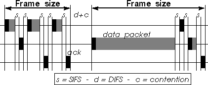
Fragmentation uses the SIFS to retain control over the medium and to send all fragments of a packet as a burst, each transmission of the burst being separated by a SIFS. Each fragment is individually acknowledged by the receiver by sending an ack message (after a SIFS), and upon reception of this ack the sender sends the next fragment (after a SIFS).
Packet Frame Grouping uses exactly the same mechanism, the contention free frame (the burst) containing many small independent packets (instead of fragments of a larger packet), which may have a different destination address.
To implement Packet Frame Grouping, the MAC needs only to include a counter to count the number of bytes sent in the current frame. Each time the MAC successfully sends a packet (i.e. receives the ack), it adds the size of the next packet in the transmit queue to the current frame size and compares it to the maximum frame size. If it is below, it sends this next packet after a SIFS, otherwise it resets the counter and goes into contention.
The model implements MAC level acknowledgments and retransmissions, and RTS/CTS (for packets larger than 250 B). This model doesn't include fragmentation (but the compatibility of Packet Frame Grouping and fragmentation has been verified in another set of simulations).
The maximum packet size is 1500 B. All other parameters conform to 802.11 [1] (CWmin = 16 ; SIFS = 28 µs ; Slot = 50 µs ; Headers = 50 B).
The main advantage of this traffic model is that it is already widely used and it allows to explore the full range of network loads and packet sizes.
To simulate those traffics, the random traffic generator is modified to use a fixed packet size (no longer random). The voice traffic still use a random interarrival time : the fact that these packets may come from another network or a TCP stack adds a variable latency, so packets won't arrive exactly at fixed intervals.
In the simulations, the load of the voice traffic is fixed at 32 kb/s, and in each packet an overhead for IP and UDP headers (32 B) is included. Because the packets are so small, the main characteristic of this type of traffic, with regard to the MAC protocol, is the mean interval between packets (the arrival rate at the MAC), the actual traffic load has a much smaller impact.
The applications on top of the network stack will emphasize this behaviour. Modern computers use some clever cache techniques to minimize the amount of network requests. The result is that most requests will be some long bursts of data over the network (that TCP will translate into long bursts of large packets). This characteristic applies to ftp, http (especially http 1.1), smb, nfs, disk sharing and print jobs.
The first TCP traffic model (TCP1)simulates a node sending a large amount of data over a protocol such as TCP. The sender sends packets of the maximum size as fast as possible. The receiving node acknowledges each incoming packet with a short packet (40 B).
The second TCP traffic model (TCP2) is a simple bimodal distribution. Each packet is either big (maximum size) or small (40 B), the probability of being small is 1/3 (this simulates medium TCP optimisation). Packets are sent as fast as the link can manage.
These traffic models don't implement any TCP flow control and congestion avoidance mechanisms, but only the packet distribution. With MAC level retransmissions, TCP should always use the full network capacity [4].
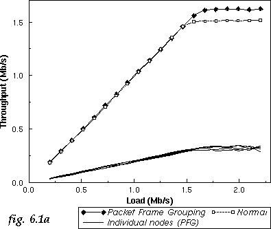
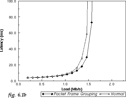
With this type of traffic, Packet Frame Grouping gives a 7 % increase of the maximum throughput (fig 6.1a) and a reduction of the average latency (fig 6.1b). This shows clearly that Packet Frame Grouping offers a significant improvement of the network efficiency.
The Throughput vs. Load graph (fig 6.1a) includes the individual throughput of each of the 5 nodes using Packet Frame Grouping to show the scheme is fair (each node can send approximately the same amount of data).
For this, four different configurations have been chosen : the previous one (5 nodes using the random traffic), an ftp transfer (a sender and receiver using the TCP1 traffic), a small TCP network (2 nodes using the TCP2 traffic) and a medium network (10 nodes using the TCP2 traffic). As explained in the model description, the last three configurations adapt to the network capacity, but for the 5 nodes using the random traffic, the load has to be adjusted : for the maximum throughput simulation, a load of 1.75 Mb/s has been chosen, and for the average latency a load of 1.45 Mb/s.
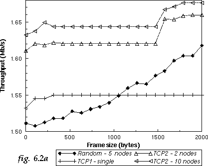
A frame size of 0 is equivalent to no Packet Frame Grouping (scheme disabled) and a larger frame size allows to group more and more packets. The first obvious result is that the improvement given by Packet Frame Grouping depends very much on the traffic considered.
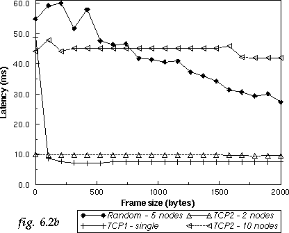
The TCP1 traffic shows almost no improvement of throughput (fig 6.2a) and a huge improvement in latency (fig 6.2b). The dramatic improvement of the latency must be seen as an artifact of the TCP1 model. The huge delay without Packet Frame Grouping (frame size = 0) is due to TCP acks being queued. In the real world, there is no way we could queue that many TCP acks in the networking stack and the card.
The lack of increase in throughput (around 1 %) could be explained by the fact that the receiver is the only node sending small packets. As those acks are generated only upon reception of data packets from the sender, the receiver has no real advantage in sending them faster, it still has to wait for the sender.
The TCP2 traffic shows no improvement in latency (fig 6.2b). In this model the packets are generated upon consumption of the previous one by the MAC, there is no queuing in the system and this latency is only the channel access delay, which could explain the lack of improvement due to the scheme. The increases in throughput (around 3 % in total - fig 6.2a) correspond to the point where the scheme is able to group two small packets and then a small packet with a large one.
To simulate the data traffic, the TCP models of the previous set of simulations have been re-used. The multimedia traffic uses the voice model (random interarrival time, fixed packet size). The load of the voice model is fixed (32 kb/s + UDP overhead), and different average packet arrival times are used (the main parameter of this model).
The network is composed of two nodes performing a data transfer (using TCP1, and then TCP2) and 4 nodes exchanging voice traffic (giving a total load of 128 kb/s). In each case, the throughput of the data traffic only and the latency of the multimedia traffic only are measured.
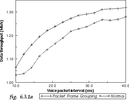
The first graph shows a large throughput improvement (around 9 % - fig 6.3.1a) of the data traffic when using Packet Frame Grouping. This is quite spectacular because, in the previous set of simulations, the same traffic (TCP1 - without the addition of the voice traffic) was showing no improvement. The fact that the small packets of the voice traffic are sent more efficiently leaves more bandwidth for the data packets.
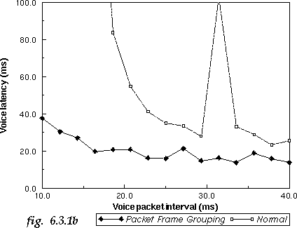
The voice traffic benefits largely from Packet Frame Grouping (fig 6.3.1b). For average packet intervals larger than 20 ms, the improvement in latency is around 50 %. Packet Frame Grouping also helps when sending packets with very short interval time (under 20 ms) with tolerable delay, where a standard MAC would not cope.
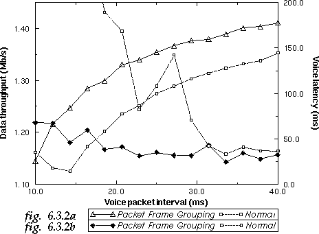
The simulation shows the same type of results when using TCP2 as the data traffic instead of TCP1. The data throughput improvement is slightly larger (around 10 % - fig 6.3.2a), and the latency improvement smaller (around 25 % - fig 6.3.2b). This smaller latency improvement could be explained by the fact that the TCP2 traffic is more aggressive that TCP1 (uses more large packets), so tends to use more of the available bandwidth (latencies in this simulation are much higher than with TCP1).
By grouping small packets into a contention free frame, the protocol gets rid of some of the contention overhead and increases the share of the medium available to an application using small packets. This scheme is easy to implement and fits naturally in 802.11 as it just reuses the principle of 802.11 fragmentation.
Simulations of the scheme have showed that it offers an improvement of the MAC in both throughput and latency. The improvement is quite limited in the case of large data transfer, but the network performance increases dramatically for a mix of data and multimedia traffics.
The next step would be to implement the Packet Frame Grouping scheme
in a 802.11 wireless LAN to study its effect in real conditions and
validate the results of the simulations.
8 References