Chromaglyphs for Pose
Determination
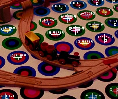
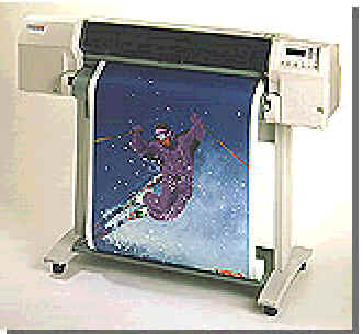 Chromaglyph wallpaper can be
printed with standard large format inkjet printers. Chromaglyphs in the background
of a complex scene allow the automatic inference of camera pose*. Given a photograph
of such a scene, each fully visible glyph can be detected automatically, even
in images with complex occluding geometry. Known 3D world coordinates of the
glyph centers are combined with extracted 2D image coordinates to compute a
projection matrix, representing camera pose.
Chromaglyph wallpaper can be
printed with standard large format inkjet printers. Chromaglyphs in the background
of a complex scene allow the automatic inference of camera pose*. Given a photograph
of such a scene, each fully visible glyph can be detected automatically, even
in images with complex occluding geometry. Known 3D world coordinates of the
glyph centers are combined with extracted 2D image coordinates to compute a
projection matrix, representing camera pose.
* [State et. al. Siggraph
‘96, Gortler et al Siggraph ‘96]
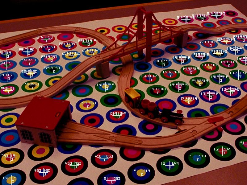
Typical input image. Full
size.
A file of correspondence points is generated for each image in
the input image set. Each line contains the 3D world coordinates
of a glyph followed by the image coordinates for the same glyph.
-943.000000  -235.000000 -824.000000 919.369202 507.107697
 705.000000  -824.000000  471.000000 313.598511  84.849167
-943.000000  -824.000000  235.000000 759.909912 156.548340
 705.000000  -824.000000  235.000000 330.811584 215.876328
-943.000000  -824.000000   -0.000000 759.685852 233.100281
 470.000000  -824.000000   -0.000000 433.729980 314.430298
 705.000000  -824.000000   -0.000000 347.122772 336.432312
-237.000000  -824.000000 -236.000000 631.291504 351.738678

                            ...

 705.000000  -824.000000 -236.000000 362.452515 448.159546
  -1.000000  -824.000000 -471.000000 582.685425 457.439697
Finally, camera pose is calculated and a transformation matrix
is created. We perform this step with Reg Willson's implementation
of Roger Tsai's camera calibration algorithm.
-1152.978614 598.702839  -285.869528 2043009.584919
  -51.087031 -25.758194 -1204.593883  734586.796646
   -0.801051  -0.461119    -0.381690    2332.827276
    0.000000   0.000000     0.000000       1.000000
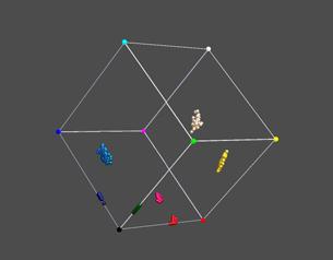
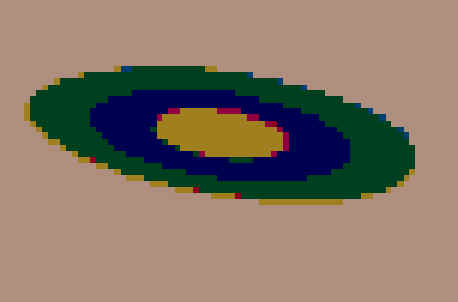
Glyph Color Space
Each glyph is composed of N
discs, each with a unique color, chosen from a set of M prototype
colors. In the case shown above N=3, M=8. The permutation of disc
color uniquely identifies the glyph and is used to lookup the 3d
coordinates of the glyph. We must reliably identify these colors
under these conditions:
- Variations in view
direction
- Shading variations due to
scene geometry
- Printing nonlinearities
and noise
- Imaging nonlinearities and
noise
The image below demonstrates
the printing and imaging nonlinearities (photoCD based) involved
in mapping the corners of the color space into imaged RGB space
for a single view. The nonlinearities are extreme and cause us to
limit the number of prototype colors to 6. We reject magenta due
to its proximity to red and reserve white as a background color.
Limitations of Nearest
Neighbor Classifiers
Determination of glyph identity
requires classifying each pixel as belonging to one of the M=6
prototype colors. A simplistic approach to this is to classify
each pixel in the image as being associated with the closest
prototype color in color space. This nearest neighbor
classification fails at boundaries between regions where pixels
see contributions from more than one color. Note the false colors
appearing in the classification below. These difficulties are
best understood by looking in color space, a 2D projection of
which is shown below. Aliased pixels are shown as small spheres
between two of the larger spheres, which represent the prototype
colors. Note small amounts of noise along the diagonal between
prototypes can perturb the pixels and cause them to be
misclassified. We choose to classify each pixel as either pure
or aliased, where aliased pixels are some threshold
distance away from their closest prototype color. We use only
pure colors for determining glyph ID’s, as these are never
misclassified.
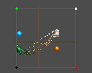
Glyph pixels in projected color
space

Raw image of a glyph
Classification of glyph pixels based on nearest
neighbors
Occluded Glyph Rejection
 Our goal is to extract the center
position and color identification of as many glyphs in each image
as possible. In the presence of occluding objects we must be
careful not misestimate glyph centers if a glyph is partially
obscured, as this would lead to inaccuracies in the estimation of
camera pose. We must also not misidentify occluding geometry as a
glyph. We employ a number of heuristics to ensure that the glyph
centers are accurately reported. The glyph extraction method
extracts connected regions of foreground colors (non-white),
classifies each pixel in the foreground region as belonging to
one of 6 prototype colors and then checks the distribution of
foreground colors.
Our goal is to extract the center
position and color identification of as many glyphs in each image
as possible. In the presence of occluding objects we must be
careful not misestimate glyph centers if a glyph is partially
obscured, as this would lead to inaccuracies in the estimation of
camera pose. We must also not misidentify occluding geometry as a
glyph. We employ a number of heuristics to ensure that the glyph
centers are accurately reported. The glyph extraction method
extracts connected regions of foreground colors (non-white),
classifies each pixel in the foreground region as belonging to
one of 6 prototype colors and then checks the distribution of
foreground colors.
- Only N=3 prototype colors
are seen in the region. Disregard any region with more
than 5% of its pixels not in the top 3 ranked, classified
colors.
- The number of pixels in
the top 3 ranked colors corresponds to a distribution
expected from a glyph geometry of concentric overlapping
discs.
- Disc regions are
concentric. The spatial centroid of the top 3 ranked
pixel colors should be within a few pixels of each other.
- Pixels in the outer band
should have a larger standard deviation of position than
those in the inner bands. The rank of the the top N=3
color histogram must match the rank of the top 3 spatial
standard deviations.
- A glyph must exceed some
minimum size to be usable.
- The glyph ID implied by
the top 3 ranked colors must have actually occurred on
the particular chromaglyph sheet imaged.

Connected region color histogram
In addition, we can classify
each pixel as being either an pure or aliased
pixel. Pure pixels are within some threshold distance in color
space to one of the M=6 prototype colors. Aliased pixels are past
this threshold distance in color space and presumably are pixels
on region boundaries that have contributions from more than one
color region. There are further tests we can apply based on this
classification.
- Exactly N=3 types of pure
pixels are seen in the region.
- Each of the N=3 top ranked
buckets must have some minimum number of pixels.
Pure pixels classification
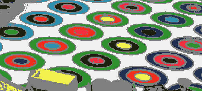
Download
a sample (.gif file, 209KB) of Chromaglyph wallpaper.
Back to top.