A Medium Access Protocol for Wireless LANs which supports Isochronous and Asynchronous Traffic
Chris Romans Jean Tourrilhes
cgr@hplb.hpl.hp.com jt@hplb.hpl.hp.com
Hewlett-Packard Laboratories, Bristol
Filton Road, Stoke Gifford, Bristol BS12 6QZ, UK.
Abstract: In this paper we present a Medium Access Control (MAC) protocol for a wireless LAN which is designed to support both isochronous (voice) and asynchronous (data) traffic. The protocol is designed for use in a frequency hopping system and uses a TDMA access protocol to support voice and a CSMA/CA access protocol to support data. A wireless LAN using this protocol can be operated as either an ad-hoc network (in which case only the data service is supported) or as a managed network under the control of a control point or base station (in which case the voice service is also supported).
Introduction
Wireless local area networks (LANs) have been predominantly used to support data applications. However recent developments, particularly the ability of PCs to deal with real-time voice in an efficient manner, and the potential for wireless LANs to become a significant networking technology for the home, have demonstrated the need for wireless LANs to efficiently support both voice and data traffic. The requirements for voice and data traffic are however very different.
|
Voice Traffic |
Data Traffic |
|
Isochronous |
Asynchronous |
|
Delay sensitive |
Not delay sensitive |
|
Minimise delay |
Maximise throughput |
|
Regular and deterministic |
Irregular and bursty |
|
Small packets |
Large and small packets |
During system design a decision is taken to optimally support one or other traffic type and this leads to the adoption of a particular access mechanism. In general wireless protocols designed for voice networks use Time Division Multiple Access (TDMA) (e.g. GSM and DECT [DECT91]) and do not handle data very efficiently, whilst those designed for data networks typically use some form of CSMA/CA (802.11 [802.11] and Hiperlan [HIPERLAN]) and do not handle voice traffic efficiently [VIS95], athough a mechanism to improve support for real-time traffic in 802.11 has been described [SOB96].
To overcome the limitations of current MAC technologies we have been investigating how to retain the advantages of both types of MAC protocols, without reducing the quality of service for each traffic type, and without increasing the overall complexity of the system.
Our goal is to be able to support high quality real-time voice conversations, and at the same time provide a high data throughput. We expect the predominant data traffic to be TCP/IP or a similar network protocol and have therefore designed the protocol with the requirements of this type of traffic in mind [BAL96]. To provide high quality voice we have chosen to use a 32 kbit/s ADPCM codec [G.726] which is identical to that used by DECT. This codec is widely used and enables us to offer good integration to the telephony network.
Network Architecture
The network and MAC protocol are designed to operate using a frequency hopping radio in the 2.4 GHz ISM band. The protocol uses a dwell period of 20 ms and the radio hardware used provides two bit rates; 1 Mb/s using 2FSK modulation and 2 Mb/s using 4FSK modulation
The network can accommodate up to 127 nodes. These nodes can be a mixture of several basic types:
- Control Point (CP) that supports voice services.
- Voice Terminal that only uses the TDMA access mechanism to communicate with a Control Point.
- Data Node that uses the CSMA/CA access mechanism and can communicate with a Control Point and other data nodes.
- Voice and Data Node which can use both access mechanisms.
The network can operate as either an ad-hoc network or as a managed network under the control of a Control Point. In an ad-hoc network all stations are equal and control of the network is distributed between the stations. In an ad-hoc network only data communication is supported.
 A Control Point is required to support the voice service and manage access to the medium to ensure delay requirements are met and also provide an interface to the phone network, enabling any voice node in the network to make and receive external voice calls (like a cordless phone). The Control Point functionality can be integrated in a PC, or it can be implemented separately in a base station.
To support higher level telephony services the MAC interfaces to the DECT protocol stack [DECT91].
MAC Protocol
The MAC protocol is designed for operation in the 2.4 GHz ISM band with a frequency hopping radio. Any system that uses this band in the US must comply with the FCC rules. Additionally since the band is unlicensed, the system must also be able to operate in the presence of other ISM band radio systems, and interference sources, e.g. microwave ovens.
The MAC protocol is essentially a hybird protocol which combines both TDMA and CSMA/CA access mechanisms. Hybrid MAC protocols are not unique [NAT92] but the protocol describes here incorporates features which ensure good performance under a wide range of conditions.
Framing
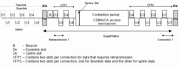
The MAC protocol uses a superframe, which incorporates two contention-free periods (CFPs) and a contention period. The start of the superframe is the point at which a station begins to hop to a new channel and ends immediately before the station starts to hop to the next channel. The duration of the superframe is fixed and is the same as the dwell or hop period. The access mechanism used during each CFP is TDMA, whilst the access mechanism used during the contention period is CSMA/CA.
Each of the contention free periods is divided into a number of pairs of fixed length slots, two per voice connection. The first slot in each pair is used to transmit voice data from the Control Point to a node (downlink) and the second is used to transmit voice data from a node to the Control Point (uplink).
In a managed network a Beacon is transmitted immediately after the hop. This Beacon is used to maintain network synchronisation, control the format of the superframe and manage when each node should transmit and receive data.
The CFP at the end of the superframe is used for the initial transmission of the voice data, whilst the CFP at the start of the superframe is used for the optional retransmission of any data which was not received or was incorrectly received. The dwell period is fixed at 20ms to provide acceptable performance with respect to latency. The length of the dwell period also means that each voice data message contains 20 ms of ADPCM data (640 bits), equivalent to an extended DECT B-field and 48 bits of control data, equivalent to the DECT A-field. In addition each packet transmitted includes the necessary MAC and PHY headers.
With a 20ms superframe the MAC can provide either 4 voice connections with a large enough CFP at the start of the frame to enable all the voice data to be retransmitted, or a larger number of connections (e.g. 6), but in this case the CFP at the start of the frame is only large enough for the retransmission of data from two connections.
The CFP in which initial transmission occurs and the CFP in which retransmission occurs are separated by a frequency hop, giving frequency diversity which is particularly important given the environment in which the protocol will operate.
At the end of the first CFP in the superframe there is a space reserved for a service slot. The service slot is used by voice nodes to communicate with the Control Point.
Each voice data packet transmitted by a node includes in the packet header a piggyback acknowledgement of the last voice data message received by the node. i.e. in the uplink packet, the voice node acknowledges the downlink packet sent by the control point. This system allows the control point to determine prior to a hop which voice data transmissions were lost, to determine the retransmissions required, and advertise these retransmissions in the Beacon at the start of the next superframe. Each voice data packet can only be retransmitted once.
The time between the two CFPs, the contention period, is used for data transmissions using a CSMA/CA protocol similar to that specified in the 802.11 standard [802.11]. The MAC uses a slotted contention scheme, acknowledgement and retransmission of data messages and a fragmentation scheme to improve performance.
If there is no voice connection active then the CSMA/CA period occupies the whole of the superframe, with the exception of the space required for the hop and Beacon, maximising data throughput.
If there is no Control Point present, then the data nodes can create an ad-hoc network in which control of the network is distributed between all the nodes.
Management
The primary function of the Beacon is to enable all nodes to synchronise to the hopping pattern of the network.
The Beacon transmitted by the Control Point is also used to manage the network during the contention free periods. The Control Point Beacon (CPB) can include a list of active voice connections (and therefore slot assignments), retransmission slot assignments for the current superframe, connection status information and paging information.
Slot assignment and synchronisation information does not change on a per frame basis, so if a node misses a Beacon it uses the information contained in the most recent valid beacon. All connection and paging status requests and information are repeated until they are acknowledged by the target node.
To optimise the performance of the protocol the Control Point performs "connection packing" to eliminate unused slots and maximise the contention period and therefore maximise data throughput
In an ad-hoc network each node schedules the transmission of an ad-hoc beacon during each dwell period. A node uses its address to determine when it should send an ad-hoc beacon preventing collision of ad-hoc beacons from different nodes. If a node receives messages from two different nodes before it is due to transmit it’s own beacon then it cancels transmission of the beacon
The service slot is used by voice nodes to send management messages to a Control Point, e.g. to request a connection from the Control Point. Since there is only one service slot it is possible for two nodes to transmit at the same time and for their transmissions to collide. Each management message is explicitly acknowledged by the Control Point in the CPB, and if there is no acknowledgement a node performs a random backoff across a number dwell periods before re-sending the message. When closing a connection, the node transmits a management in its voice slot.
Simulation models
A set of models was developed using the Bonesâ
Designerä
simulation environment to verify and test the protocol.
MAC model
The MAC model implements the complete channel access mechanism for the protocol, with only a few minor simplifications. The model does not include all the management functionality, but its impact in terms of medium occupancy has been taken into account.
A random channel hopping model is used with the channel parameters being recalculated after each hop.
Channel model
The channel model is a simple radio channel model, including node to node attenuation (as a function of the distance), Rayleigh fading (calculated on a per packet basis) and antenna diversity. The model has been validated by computation of the received packet failure rate versus pathloss in a Gaussian channel. The bit rate used is 1 Mb/s, transmitted power is +20 dBm and sensitivity is -80 dBm.
Traffic models
There are two different traffic models, one for voice traffic and the other for data traffic.
The voice traffic model consists of a bi-directional constant load voice stream in which each voice conversation is assumed to be a 32 kbit/s bit stream. This bit stream is packetised (a packet of 640 bits is generated every 20 ms) to fit into the voice service offered by the MAC.
The data traffic model is a classical random traffic generator: all packet sizes are uniformly distributed in the interval ]0 ; max packet size] and packets arrive at the MAC following a Poisson process (random interarrival time with negative exponential distribution).
Interferer models
To evaluate the robustness of the protocol, we have designed models of the interferers most commonly found in the 2.4 GHz frequency band. The Frequency Hopping (FH) and Direct Sequence (DS) interferers represent 802.11 (or similar) systems operating at a distance of 5m from our system. The system parameters for the interferers are: transmitted power +20 dBm; bit rate 1 Mb/s for the FH, and 2 Mb/s and 11 chips for the DS interferer.
The microwave oven model is based on measurements of domestic microwave ovens in the 2.4 GHz band and the NTIA report [NTIA94]. The model uses a 50 % duty cycle, synchronised to the mains power supply (16 ms period). Each ‘on-period’ starts and ends by a transition phase, which is of short duration (around 1 ms), wideband (30 MHz) and has a power randomly selected in the range –15dBm to +15dBm. For the remainder of the on-period the transmission is narrow band (2 MHz) and high power (+25 dBm). The microwave oven is located 2m from our system.
Simulation results
Voice traffic - 8 slots
For voice communication the main requirements are a guaranteed maximum delay and a low data loss. The design of the MAC protocol guarantees that the delay is below 20 ms.
The definition of low data loss is dependent on the codec and the mechanism used to transmit the data. It has been shown [VAR94] that the ADPCM codec can accommodate the loss of entire packets and can cope with a few percent packet loss. The following results show the packet failure rate. The effect of beacon loss has also been taken into account in the simulations.
Because of the way the protocol is designed, the voice traffic has absolute priority on the medium and is not affected in any way by the data traffic. The following set of results applies to the voice traffic whatever the load of the data traffic or the number of nodes using it.
Figure 1 shows the raw packet failure rate experienced at the physical layer in each of the four different environments, no interferer (normal) and with each defined interferer, with increasing distance between the transmitter and the receiver. The figure shows the results for a fully loaded system (4 voice connections). Only in the absence of any interferer is the packet failure rate acceptable (less than 3%) for the required range. The packet failure rate in the presence of a DS interferer or a microwave oven is unacceptable.
Figure 2 shows the packet failure rate at the top of the MAC, in the same conditions. A comparison of the two curves illustrates the effect of adding the full MAC functionality, especially retransmission (with frequency diversity). The previously unacceptable packet failure rate is significantly reduced. In the absence of an interferer or in the presence of a FH interferer the packet failure rate is negligible for the full range. In the presence of a DS interferer or microwave oven the failure rate remains less than 3% up to a range of 40m.
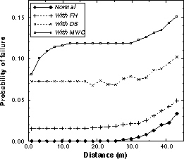
Figure 1: Physical Failure vs Distance
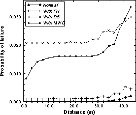
Figure 2 - Packet failure vs Distance
Data traffic - 2 nodes
The CSMA/CA scheme used is designed to provide fair access to the medium, good data throughput and be stable. In addition since CSMA/CA allows multiple retransmissions of failed packets the protocol guarantees a very high reliability.
For CSMA/CA the important results are the throughput available to the system and the average network delay experienced by packets. The results presented are for a two node system. The load for each node has been set to 700 kbit/s to saturate the link.
The length of the period allowed for CSMA/CA traffic in the protocol is bounded by the number of voice connections. The impact on data throughput of increasing the number of voice connections is shown in Figure 3. The impact on the delay is shown in Figure 4.
Figure 3: Maximum Throughout vs Distance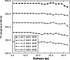
Figure 4: Network Delay vs Distance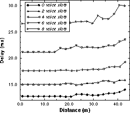
The throughput drop per voice connection is around 80 kb/s, and with 4 voice connections (8 voice slots), CSMA/CA still delivers a high throughput (greater than 250 kbit/s).
As the number of voice slots increases so does the delay as data packets have to wait for TDMA traffic to finish. The delays however remain well below 50 ms and so are compatible with internet multimedia types of applications. In the case where we have only one voice connection, the CSMA/CA delay is below 15 ms, which is compatible with high quality TCP/IP multimedia applications.
Simulations of the behaviour of the CSMA/CA part of the protocol for multiple nodes and also in presence of the interferers defined previously have also been done. These simulations gave results similar to those observed with other CSMA/CA protocols (such as 802.11 [802.11]).
Conclusions
The MAC protocol described in this paper is designed for use on a frequency hopping system that operates in the 2.4 GHz ISM band. The protocol provides a mechanism by which voice and data services can be supported on the same system.
The voice part of the protocol is based on TDMA, and provides up to 4 voice connections (32 kb/s bidirectional, 20 ms guaranteed latency). A real time retransmission mechanism with frequency diversity guarantees a high quality of service even in the presence of interferers.
The data part of the protocol is based on CSMA/CA, has an ad-hoc architecture and interfaces transparently with TCP/IP and other data networking stacks. The data service runs in the space left by voice transmissions and maximises the use of the bandwidth to provide a high throughput (larger than 500 kbit/s node to node).
The simulation results show that up to 4 voice connections can be supported with acceptable packet failure rates (Figure 2) and that high data throughputs with acceptable delays can be obtained whilst supporting a number of voice connections (Figure 3 and Figure 4).
Acknowledgements
We would like to acknowledge the work of the following during the development of this protocol; Louis Gaiot and Kevin Negus of Hewlett-Packard and Paul Morris of Symbionics.
References
[802.11] IEEE 802.11 : Wireless LAN medium access control (MAC) and physical layer (PHY) specifications. IEEE.
[BAL96] Hari Balakrishnan, Venkata N. Padmanabhan, Srinivasan Seshan and Randy H. Katz. A comparison of mechanisms for improving TCP performance over wireless links. Proc. of ACM SIGCOM ’96.
[DECT91] ETR 015. DECT Reference Document. March 1991, ETSI.
[G.726] CCITT Recommendation G.726. "40, 32, 24, 16 kbit/s Adaptive Differential Pulse code Modulation (ADPCM). Geneva 1990.
[HIPERLAN] Radio equipment and systems (RES) ; High Performance Radio Local Area Networks (HIPERLAN), Type 1, Functional specification. ETSI.
[NAT92] K.S. Natarajan. A hybrid medium access control protocol for wireless LAN. 1992 IEEE International Conference on Selected Topics in Wireless Communications. pp 134-7.
[NTIA94] Radio spectrum measurements of individual microwave ovens. NTIA report #94-303.
[SOB96] J.L. Sobrinho and A.S. Krishnakumar. Distributed multiple access procedures to provide voice communications over IEEE 802.11 wireless networks. GLOBECOM ’96.
[VAR94] V. Varma, M. Thomas, S. Konish, L. Seltzer and D. Goodman. Performance of 32 kb/s ADPCM in Frame Erasures. Proc. of IEEE VTC ’94.
[VIS95] Matthijs A. Visser and Magda El Zarki. Voice and Data transmission over an 802.11 Wireless network. Proc. of IEEE PIMRC ’95.